Choosing the Design Point for Pilot Plant Equipment
March 20, 2017
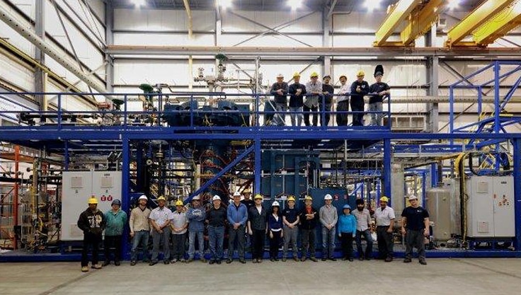
This pilot plant, designed and built by Zeton, had a reactor with an extremely challenging design point: 2500 psig at 1200 C.
For an established process, choosing the temperature and pressure ratings of equipment is a relatively straightforward exercise. However, choosing the maximum operating pressure and temperature combination for major pieces of equipment in a pilot plant is much more challenging.
Choosing the correct combination, or design point, is one of the key decision processes in any pilot-plant project, meriting significant analysis and thought. Choosing a design point that is too low can render a plant useless, but even in a pilot plant, it may not be in the best interest of the project as a whole merely to guess high. Further, choosing a point that is inappropriately high can increase the cost and delivery schedule of the pilot plant by a significant fraction without providing any meaningful benefit. An inappropriately high point may also hamper operation of the full plant by unnecessarily limiting the types of closures, equipment, valves, and instrumentation that can be used, resulting in increased downtime or a reduction in the ability of the plant to deliver the desired measurements, products, and data in a timely fashion.
A breakpoint analysis for the proposed materials of construction should be carried out as a preliminary design exercise, in an effort to establish an appropriate design point. By identifying the natural limits for pressure and temperature for the required materials of construction, natural breakpoints for the design and pressure and temperature combinations for various pieces of equipment can be determined. It goes without saying that crossing a natural breakpoint can come with a significant cost, schedule, or operability penalty and should not be done lightly.
Figures 1 and 2 demonstrate some of the natural breakpoints applicable to process equipment and piping systems, based on materials of construction and utilities.
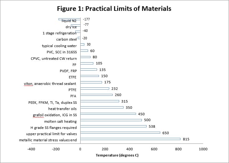
In Figure 1, the thermoplastic materials (PVC, PP, PVDF, FRP) temperature limits given are based on the practical use of the material as pipe or tubing, which of course greatly depends on pressure. Some of the materials may be extended to higher temperature service as linings on metallic components for corrosion resistance. Other materials such as PTFE, PFA, ETFE, the elastomers, PEEK etc. are listed with the maximum continuous service temperatures at which they can be reliably deployed as sealing materials as gaskets, packings, valve seats or as linings etc.
Also in Figure 1, a number of “rules of thumb” for the practical upper or lower limit of various utilities (cooling water, hot oil, refrigerant, molten salts) are listed. These are intended for rough guidance only, but serve as a useful reference for scoping purposes during flowsheet development.
Maximum Operating Pressure and Temperature Versus MAWP/T
Maximum operating pressure and temperature are distinct from maximum allowable working pressure (MAWP) and temperature (MAWT) of vessels, valves, piping/tubing systems, or equipment. The former is determined by process considerations, while the latter is calculated based on actual wall thicknesses, flange ratings, and gasket or seal performance. It is common for pilot equipment to have multiple pairs of MAWP and MAWT for various service conditions.
Depending on the type and specification of relief devices used for overpressure protection and the desired reliability of operation, the maximum feasible continuous operating pressure for a system will likely be between 70% and 85% of the MAWP of the pressure-limiting device(s) protected by the relief valve(s) or rupture disk(s). Setting a maximum operating pressure at less than 1/0.7 = 1.43 times the maximum desired operating pressure is risky without a detailed knowledge of the overpressure protection strategy for the plant.
MAWT is set as a prudent margin above the maximum sustained mean metal/material temperature anticipated during normal pressurized operation. Brief excursions beyond this temperature are permitted in both ASME VIII and B31.3 under pressure, and prolonged exposure while unpressurized may or may not be possible depending on the design and construction of the components. The prudence margin between maximum operating temperature and MAWT depends on the service and the variability expected in that service. Unlike for pressure, passive temperature relief is not a code requirement, leaving the nature and robustness of overtemperature protection to the designer’s engineering judgment- from a code perspective at least. Electric heaters (the subject of a future article) have some electrical code requirements in this regard.
Pushing the temperature limits of materials is routine in pilot plant design. At temperatures above 1000 F in metallic materials of construction, the properties of materials used in design are typically time dependent, meaning that creep is the primary worry. Creep takes time to occur. In pilot equipment, where campaigns might last a couple weeks to a month, the risk of a creep-related failure may be fairly easily mitigated with proper inspection and maintenance. That is probably not true in the commercial plant though, but once you get to that design you will have better data upon which to set appropriate limits.
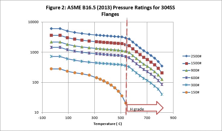
The ASME B16.5 flange table for 304 stainless steel (Figure 2) is listed as an approximate reference. Flanges made of other alloys will have ratings higher or lower than those listed, depending on temperature. Often, in carbon steel lines or on carbon steel vessels, instruments such as flowmeters and control valves with stainless steel flanges are used, and the MAWP of these components frequently limit the MAWP of the resulting assembly.
Flange ratings are often used as a natural breakpoint for pieces of process equipment and for piping, particularly at the scoping or basic design level. When a vessel or pipe line is designed such that the flanges set the MAWP, the design is termed to be “flange limited”. Flange limited design offers certain advantages to both the plant designer and the operator:
- the ASME B16.5 table gives a natural MAWP/T reference for extending the design point to higher temperatures, or higher pressures at more limited temperature, should desired operating conditions change in future
- if the flanges limit the MAWP, an over-pressure event should lead to flange leakage before failure, though there is no guarantee whatsoever that this will happen in practice
Flange ratings also serve as a convenient measure of the ease with which other components (valves, instruments etc.) may be procured, and at what cost. While 150# and 300# components are common, each increase in flange class beyond 300# may be thought of as reducing the options for the selection of valves and instruments and some other components by roughly a factor of three – with cost sometimes increasing by a similar factor…
It should be noted that both the ASME VIII-1 pressure vessel code and the ASME B31.3 pressure piping code, permit any component to limit the MAWP of the resulting vessel or piping design. A design may be limited by a shell or head or nozzle neck, by flanges or flange bolting, or by the wall thickness of pipe or tubing. It may also, in practical terms, be limited by the MAWP of any component connected to that piping system: any instrument, valve, pump or component thereof may set the MAWP for any section of the plant, and hence determine the maximum setting of required relief devices to protect against overpressure. In most cases, the optimal design for the overall pilot unit will not be fully flange-limited, as some other practical limitation will come into play before the flange limit is reached.
It should not be forgotten that the MAWP not only sets the relief pressure, but the MAWP (and MAWT) also set the pressure at which the code-required pressure integrity test (mis-described in ASME B31.3 as a “leak test”), which must be carried out as part of the quality assurance on every piping and tubing system. This test may only be waived by the owner for Category D (nonhazardous) piping systems (air, water etc.) in favour of an in-service test. The pressure integrity test, which is carried out at a multiple of the MAWP determined by code, may be carried out hydrostatically or pneumatically if hydrostatic testing is not deemed practical (frequently the case in pilot plants). Pressure integrity testing is required after fabrication, and is usually required (and strongly recommended!) after any substantial alteration of the piping. Some components, including all relief devices, must be removed prior to carrying out this test. By prudent selection of the components based on prior knowledge, it may be possible to leave many components in place for this test without damage.
True leakage testing is generally carried out after fabrication, shipment and flush-out, with all components installed, and is carried out at maximum operating pressure or a small multiple thereof. The requirements for pre-operation leakage testing vary greatly with the nature and hazards of the service.
References
ASME B16.5 (2013): Pipe Flanges and Flanged Fittings.
ASME B31.3 (2014): Process Piping: ASME Code for Pressure Piping. See particularly section 345 “Testing”