How to Choose the Right Electric Motor for the Chemical Process Industry – Part 3 of 5
October 30, 2018
Operating an electric motor in a hazardous location poses risks that range from production downtime to injury and death. In this series of articles, learn how to select the appropriate motor for your operating environment in the chemical process industry.
Class I, Division 1 Motors: An Overview
In this article, we will look specifically at Class I, Division 1 motors. Specifically, we will look at what these motors are built for and best practices for their operation.
Casing and Design
Motors for use in environments deemed Class I, Division 1 must be built and labeled as explosion-proof. An explosion-proof motor has several characteristics. Most importantly, the motor must be constructed in such a way that it will be able to completely contain an internal explosion without rupturing. Designing such a motor is not a simple task, and a lot of research and careful consideration of the strength of materials used in the enclosure and the hardware has gone into a Class I, Division 1 electric motor.
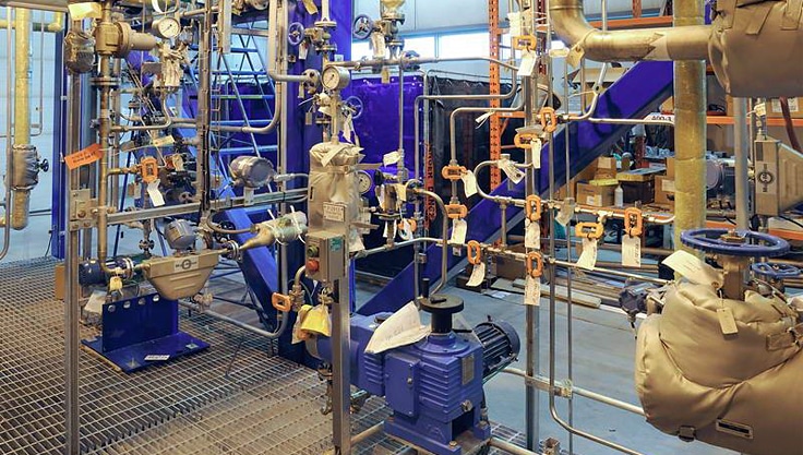
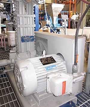 Figure 1. Explosion proof motor running a compressor at Zeton.
It is important to note that an explosion- proof motor is not necessarily designed to prevent an explosion, but only to confine an explosion within its housing. In fact, explosion-proof motors are designed under the assumption that over time the motor’s internal atmosphere will become the same as the hazardous operating environment and an internal motor fault could then cause an explosion within the motor.
If an explosion does occur within the motor, hot gases must be able to escape after an initial buildup of pressure upon ignition. A defining characteristic of explosion-proof motors is that they are constructed in such a way that any hot gases escaping the enclosure are forced to exit through long, narrow openings known as “flame paths.” As gases travel along these paths, flames must be quenched and the material must be cooled to a temperature low enough to prevent a further explosion in the external hazardous atmosphere. A typical flame path can run along the shaft of an electric motor or be designed into flanged and threaded joints in explosion-proof enclosures.
The hazardous material group that a Class I, Division 1 motor will operate under provides further guidance on the construction details required. In general, motors built for groups with more-severe explosion hazards require stronger enclosures and longer flame paths with tighter tolerances. The Group A gas, acetylene, for example, is considered to have the most violent explosion when ignited of any of the groups. Thus, explosion-proof motors for use in Class I, Division 1, Group A locations require the highest enclosure strength. Flame paths must also be longer and tighter for Group A locations than, for instance, Group D environments containing only propane.
Surface Temperatures and T-Codes
In addition to having an explosion-proof enclosure, motors for use in Class I, Division 1 locations must not develop surface temperatures hot enough to cause spontaneous ignition of hazardous gases in the external atmosphere. The motor is assigned a temperature code, or T- code, that identifies the maximum temperature of surfaces subject to contact with hazardous materials. The indicated maximum temperature applies under all conditions, including burnout, overload, and locked rotor. Table 1 shows the T-codes and corresponding maximum temperatures for the NEC/CEC and IEC classifications.
When purchasing an electric motor, the motor’s T-code should be correlated with the AIT of the hazardous gas (or mixture) in the area surrounding the working environment.
Table 1. T-Codes for NEC/CEC and IEC Classifications
| Maximum Surface Temperature |
|||
|---|---|---|---|
| NEC/CEC T-Code | IEC T-Code | °C | °F |
| T1 | T1 | 450 | 842 |
| T2 | 300 | 572 | |
| T2A | 280 | 536 | |
| T2B | T2 | 260 | 500 |
| T2C | 230 | 446 | |
| T2D | 215 | 419 | |
| T3 | 200 | 392 | |
| T3A | T3 | 180 | 356 |
| T3B | 165 | 329 | |
| T3C | 160 | 320 | |
| T4 | T4 | 135 | 275 |
| T4A | 120 | 248 | |
| T5 | T5 | 100 | 212 |
| T6 | T6 | 85 | 185 |
Consider, for example, a Class I, Division 1 location containing gasoline, a Group D material. The AIT of gasoline falls in the range of 246°C and 280°C. Considering the lowest value in the range, a motor that is to be used in such a location must have a T-code rating of at least T2C. In other words, to ensure that the gasoline will not spontaneously ignite when it contacts the motor’s enclosure, the surface temperature of the motor cannot exceed 230°C.
Nameplates
The number of classifications needed to ensure safe electrical equipment can be daunting. And while the trained eye may be able to spot an explosion-proof motor enclosure, determining exactly what group or groups it is suitable for and the T-code rating of the motor is not immediately identifiable. This is why there is a legal requirement that manufacturers supply electric motors with nameplates that clearly display the class and group(s) for which the explosion-proof motor is appropriate, along with its T-code rating. This information can be included on the main motor nameplate or presented on a separate nearby nameplate (Figure 2).
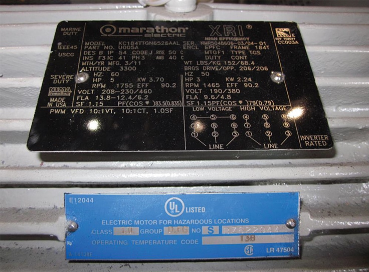
Figure 2. This nameplate indicates that the motor is rated for use in a Class I, Group D location and has a T-code rating of T3B. Note that the motor is also rated for use in a Class II (Groups F and G) environment.
The motor in Figure 2 was used to run a compressor in a biofuels pilot plant, the blue nameplate shows that it is rated for both Class I and Class II environments and Group D, F, and G materials. Its operating temperature code (T-code) is T3B.
In the next article in this series, we will look at Division 2 electric motors. In particular, we will look into the differences between motors in these divisions and what considerations go into purchasing and working with one motor or the other.