Design Inputs for Pilot Plants: Lab Data and Simulations
March 6, 2017
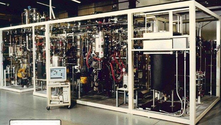
This pilot plant, designed and built by Zeton, produces customer evaluation samples of copolymers.
When developing an equipment design project, it is best to start with a fully developed process flow diagram with a complete mass and energy balance evaluated at the desired operating point. Unfortunately, one of the purposes of most pilot-plant projects is to provide that very data for the potential full-scale facility. If you wait for the flowsheet and the mass and energy balances to be nailed down completely before beginning the design exercise for the pilot plant, you will never get started.
Pilot plants are meant to be the safe places where uncertainty and risk are reduced and multiple potential operating cases can be tested. Indeed, operation outside the optimum conditions in pilot plants is necessary to establish where the optimum conditions truly lie for full-scale operations. And while there is no question that process flowsheet simulations and designed lab experiments can help avert major pitfalls, batch lab data and simulations cannot substitute for continuous pilot-plant data.
The difficulty every process development pilot-plant designer faces, then, is how to balance safety with the need for real-life data. This balance is best found in knowing when, where and how to use the power of human creativity and the power of computer simulation.
Harnessing the Power of Human Creativity and Experience
We at Zeton begin our design work with the knowledge and ingenuity we find in our engineers. We have a wealth of non-proprietary specialist knowledge about how to accomplish various unit operations efficiently at the pilot scale, based on the successful completion of hundreds of pilot plant projects. That said, we often join the process development effort on a new project after much hard work has been carried out by our clients in the laboratory, and then in putting together a “data package” as an input to the design process. Frequently, some of that work is a totally wasted effort, because it was spent answering the wrong questions, leaving key questions unanswered, or trying to answer necessary questions for commercialization at the wrong stage in the development program.
We recommend that clients use the practice of bench scale engineering in process development (Szabo, 2004). This requires bringing together process chemists and technicians and process and design engineers, hopefully including Zeton as a preliminary engineering partner, as early as possible in the development program to create a hands-on multidisciplinary team. Together, the broader team’s members are able to yield more complete and accurate information for the design of a successful pilot plant than they would by working as separate teams or coming together later in the process.
Harnessing the Power of Simulations
One of the key products of the pilot plant program should be a validated process simulation. And the preliminary simulation, augmented with lab data, is the key starting point for the design of the pilot facility.
Lab data and simulations provide the necessary composition information, thermophysical properties and duties to permit the pilot plant designer to size vessels, heat exchangers, pumps, and instruments and to select materials of construction. While the reactions themselves are generally a “black box” in the simulator with composition information filled in based on actual laboratory reactor testing, the simulation output is needed to fill in the rest of the flowsheet. It is a richer and more accurate source of information than the lab testing data for some process steps, particularly heat transfer steps which are confounded at the lab scale due to unfavourable surface area to volume ratio at small scales.
We have found that rather than establishing a single design point based on a simulation, it is often necessary to use simulation data to parameterize the design and establish an operating range for each piece of equipment in the pilot plant. The process design of the pilot plant can then be evaluated across the full parametric range to ensure that the plant has the capacity and turndown you need to handle a wide range of operational cases.
You may need to select a more flexible device or multiple pieces of equipment or instruments, or you may even need to design different process approaches to cover the range which really need to be tested. And sometimes it is simply necessary to re-evaluate the operating range you think you need to test, in terms of available instrumentation or other process equipment, and set more realistic expectations.
Guidance for Pilot Plant Simulations
We know that the process engineer tasked with simulating a pilot plant flowsheet for a new process has a very tough job. A quick poll of Zeton’s design engineers has produced a few cautions for the process simulator, to avoid problems we frequently see:
- Make sure to implement a basic pressure profile. Fluids don’t move from place to place without a driving force, and they don’t flow through equipment like packed beds and heat exchangers without losing some pressure. Applying an elementary pressure profile will help you identify missing pumps or compressors. We suggest that in the absence of other information, for processes operating at substantial pressure it is best to allow at least 5 psi (1/3 bar) as a starting point pressure drop across each flow control valve, flowmeter, heat exchanger, packed bed etc. Allowing the same rough pressure drop for frictional loss through each set of lines is also a prudent first guess. If you’re operating under vacuum or near atmospheric pressure, throw out these rules of thumb and get an equipment design engineer involved to get more realistic estimates. The equipment designer will refine the pressure profile wherever it is tight based on better estimates of the real losses of the selected equipment.
- With few exceptions, you don’t need to trouble yourself over a similar “thermal profile”- we’ll use tracing to keep your streams hot or cold for you to best simulate the commercial flowsheet, where heat loss or gain isn’t nearly as troublesome as it can be in a pilot plant. However, we need to know if there are any lines where heating or cooling or the lack thereof will cause damage or operational problems: condensation leading to corrosion, solidification or crystallization leading to plugging etc. Often these problems have already shown up in the lab and need to be communicated to the designer- don’t assume they’ll just know!
- Please don’t use stream mixers, valves or other pieces of passive equipment to add or remove heat. One can “cheat” the simulator to do that easily enough, and we frequently see that done as an aid to simulation convergence. The real process will need a heat exchanger, and the designer will need its duty and the thermophysical properties of each stream to design it. It is better to put the exchanger into the flowsheet.
- When a piece of process equipment legitimately adds or removes heat as part of its function (i.e. a reactor with heating or cooling, or a distillation column with reboiler and condenser), please make sure you call out the heat duties so the designer knows what needs to be provided.
- For exchangers used for vaporization or condensation of mixtures or where inerts are also present, we’ll need the heat release curves.
- When in doubt, generate the simulation’s basic “unit operation” report for each heat exchanger and piece of separations equipment, and supply that to the designer as a starting point- often, it contains necessary information missing from the stream summaries.
- Make sure you provide all the thermophysical data needed for sizing purposes on each stream: we’ll always need the density, heat capacity, thermal conductivity and viscosity for each phase (vapours and liquids) at minimum. For liquids we’ll also need the vapour pressure. For gases, we’ll need Cp/Cv and compressibility. For gas/liquid contacting systems, we’ll need the liquid surface tension. When it comes to slurries and liquid/liquid mixtures, mixed stream data can be scarce and untrustworthy, but please at least provide any properties information for the solid and each liquid that are known.
- The obvious cautions about selecting the right thermodynamic equation of state and using real VLE data to validate the simulation’s output whenever possible are a given.
A solid simulation with these cautions taken into account will minimize the amount of labour, and hence the cost of preliminary design work for the pilot plant. If your firm doesn’t have the simulation skills to do this work, we can help you make the necessary connections.
References
Szabo, P. (2004). Between lab and pilot plant. In Process Development Symposium Proceedings. Chicago: American Institute of Chemical Engineers.